
Case Study
IOCON – A controller for high-stress rover missions
IOCON is a physical controller for the remote exploration of the lunar surface. It bundles six axes of movement of a gripper-arm robot into one interface that works without classic buttons and keeps the system state visible through the position of its own parts. Created in the course Interface Design 1 at HfG Schwäbisch Gmünd.
- My Role
- Concept Interaction Design Usability
- Team
- Annika Feist (opens in a new tab)Magalí Wilhelm Miret (opens in a new tab)Tobias Wallisch
- Context
- Interface Design 1 with Usability 2nd semester HfG Schwäbisch Gmünd Supervised by Prof. Michael Schuster
Problem Statement
In high-stress missions, every misread control can cost the mission.
A radio signal takes around 2.6 seconds to cover the 384,400 kilometres to the Moon and back — time in which the operator cannot see the effect of their input. A JPL analysis of 1,580 anomaly reports from the Voyager and Magellan missions attributed 38 percent of incidents to human error, while behind every input sit payloads on the scale of the ESA lander Argonaut, with a contract volume of €862 million. The controller therefore has to keep the robot's state physically visible.
Guiding question
“How can we design a controller that prevents misuse even under extreme stress?”
Concept
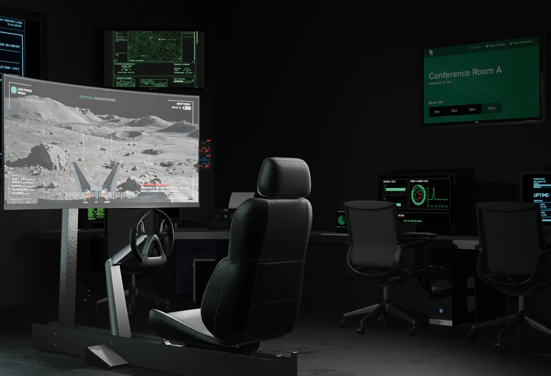
For a gripper-arm robot set by the course, we developed a controller that makes driving and gripping controllable through a single control element. Two rounds of testing with 16 people disproved our original concept for the crab walk and led to a new solution. The result is a working prototype on a robot simulation, complemented by a design prototype for the control centre.
In detail
01Research
The task
384,400 kilometres separate a safe ground station from an alien environment. A control system has to work across exactly this distance without the operator losing contact with what is happening.
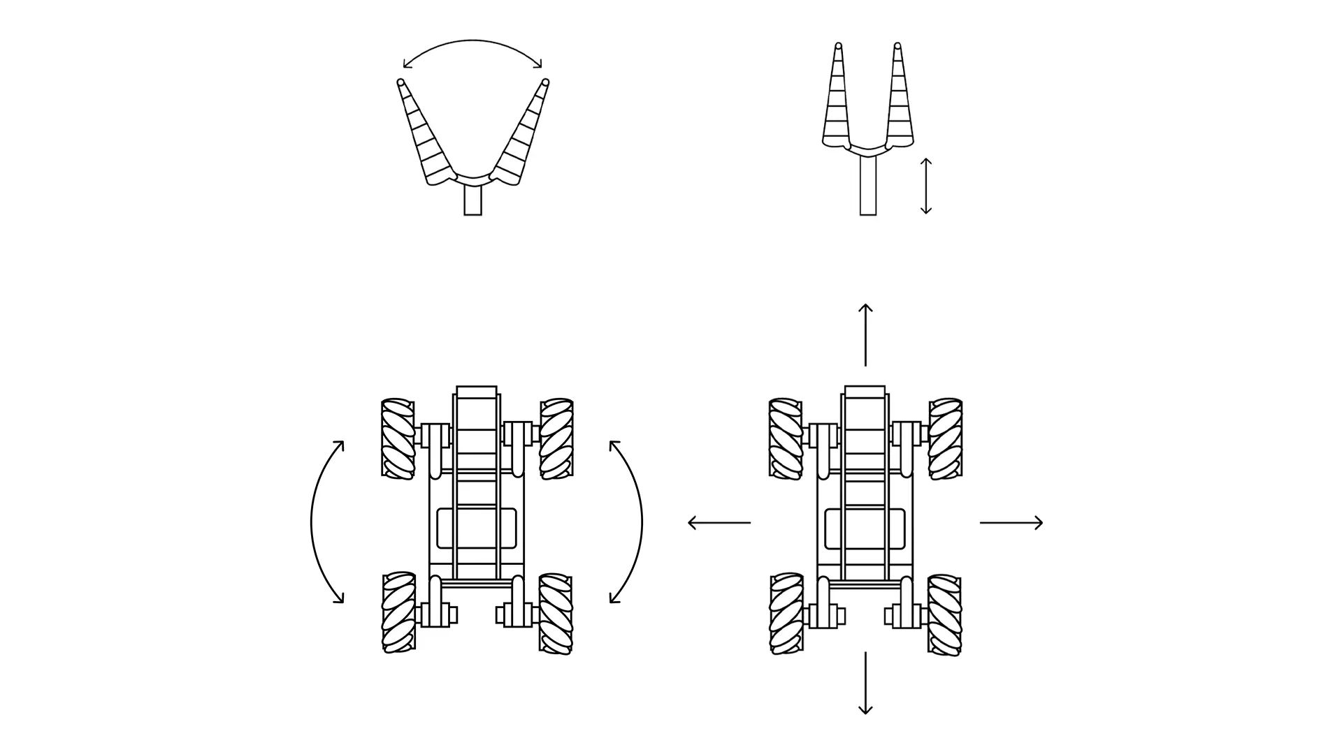
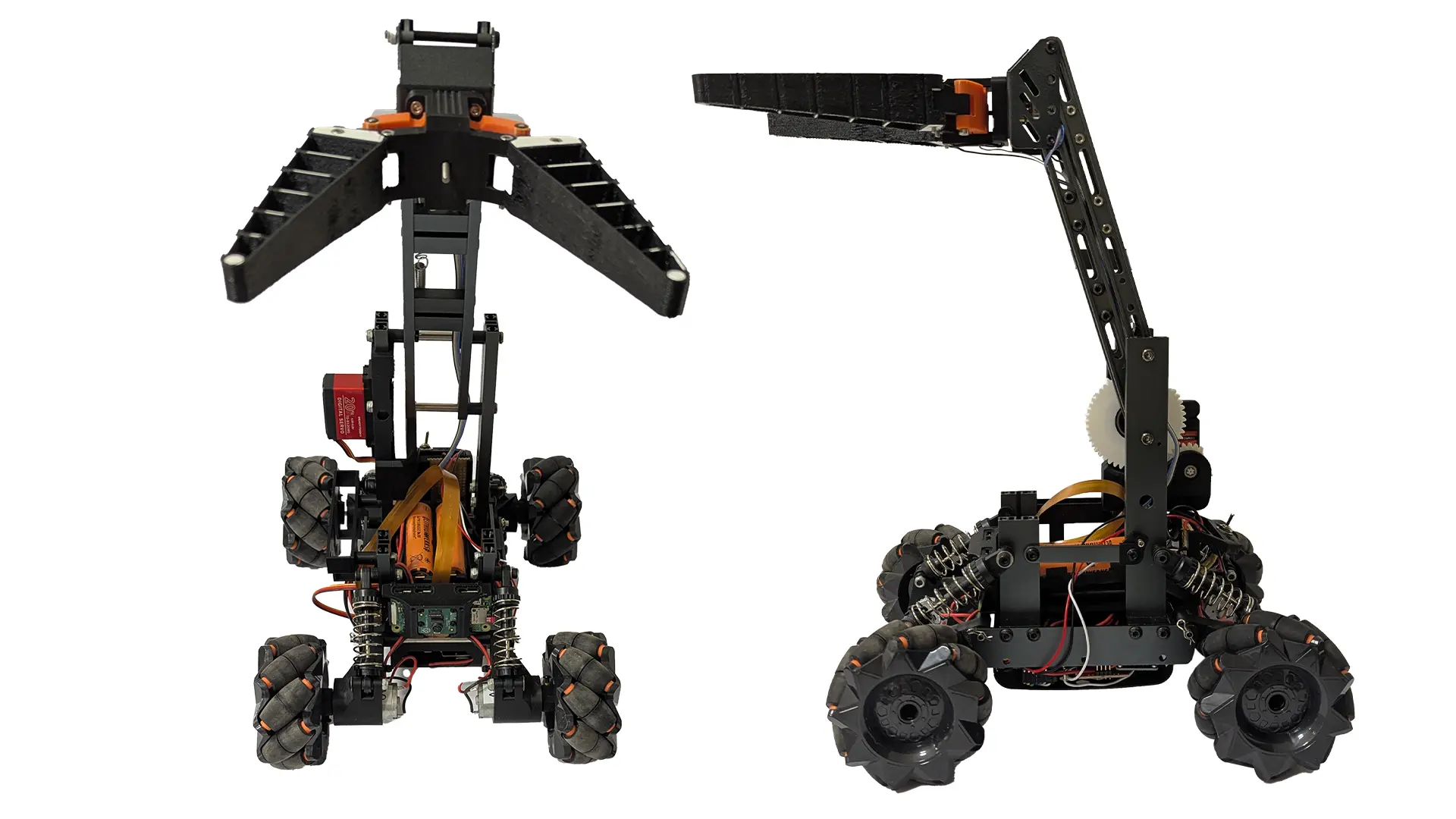
The gripper-arm robot was set by the course. Our task was to conceive and design an interactive prototype that translates its functions onto a physical interface. Six axes had to be covered: forward and backward driving, steering, crab walk as omnidirectional movement, the vertical adjustment of the gripper arm, and its opening and closing.
The use case
The usage scenario was ours to choose. We settled on the exploration of the lunar surface and the remote-controlled securing of rock samples from a control centre on Earth, specifically a controller for the European Space Agency. The target group is mission operators, i.e. trained specialists.
That shifts the standard the design has to meet. What matters is reliable feedback under latency; self-explanatory ease for laypeople comes second.
The constraint
Control across this distance is delayed. Whoever makes an input only sees its result on the monitor later. If the interface itself gives no account of its own state, uncertainty grows in that gap, and with it double input.
That became our guiding principle: the controller has to physically show which movement the robot is currently executing, or last executed.
References
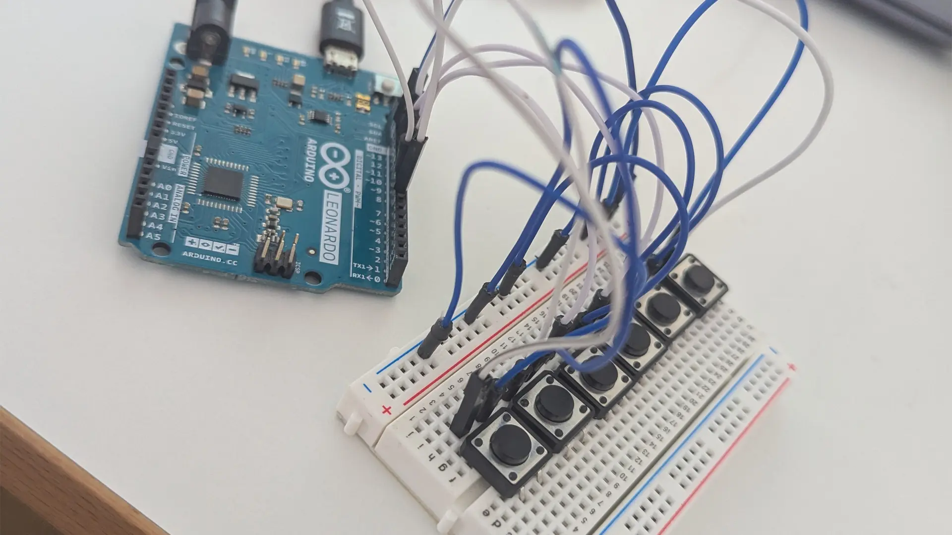
We used the first lessons to understand the robot's functions through simple circuits built from Arduino boards and buttons. In parallel, we drew on existing devices as references, in particular controls from helicopters and aircraft as well as the setup of racing simulators.
02Decisions
A ring instead of buttons
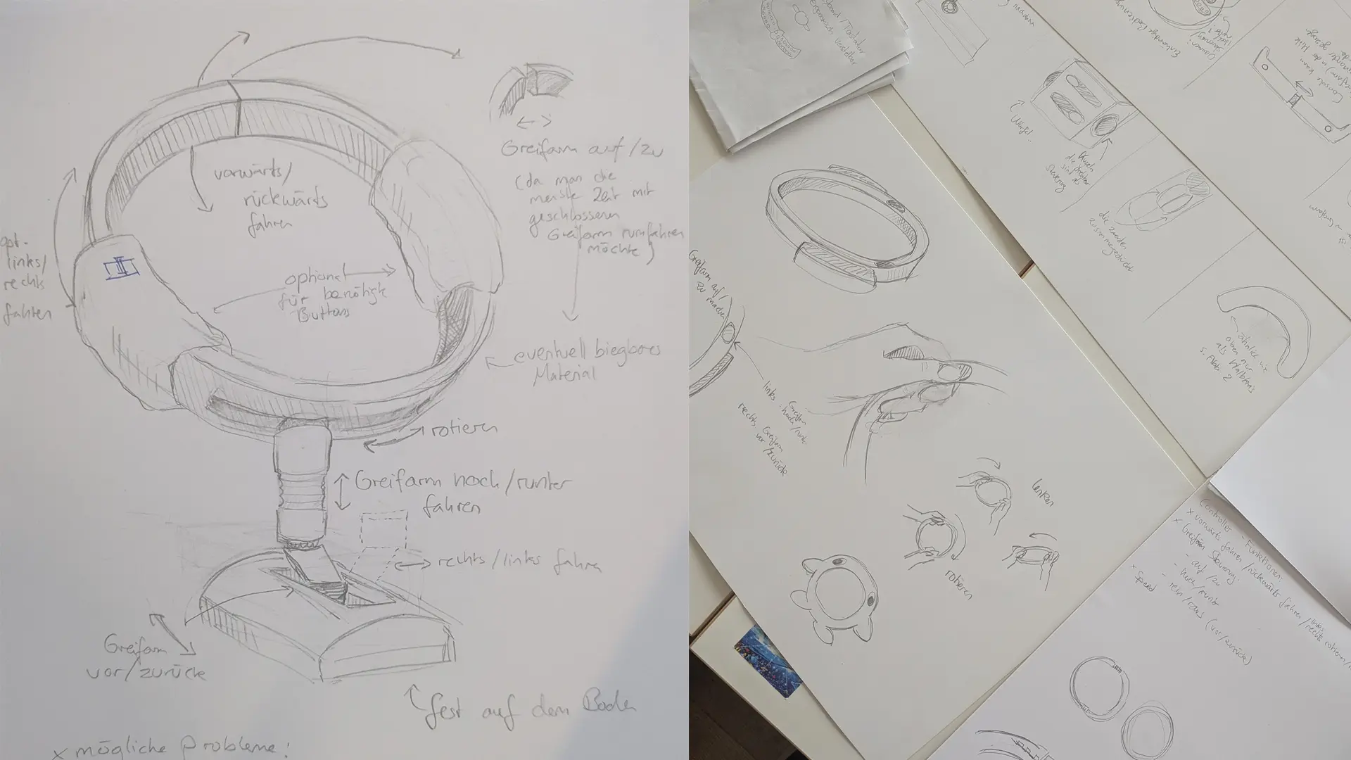
After several Crazy-8 sessions and a series of discarded control concepts, a ring-shaped element prevailed. A recess at the top and joints in the lower half allow the ring to be opened and closed. That let us translate one robot function directly into a hand movement.
Forgoing classic buttons was a deliberate decision. Instead of small inputs that leave no trace once released, we wanted larger body movements whose result stays visible on the device. An open ring holds the system state in place, even while the image from the moon hasn't caught up yet.
One joint for two axes
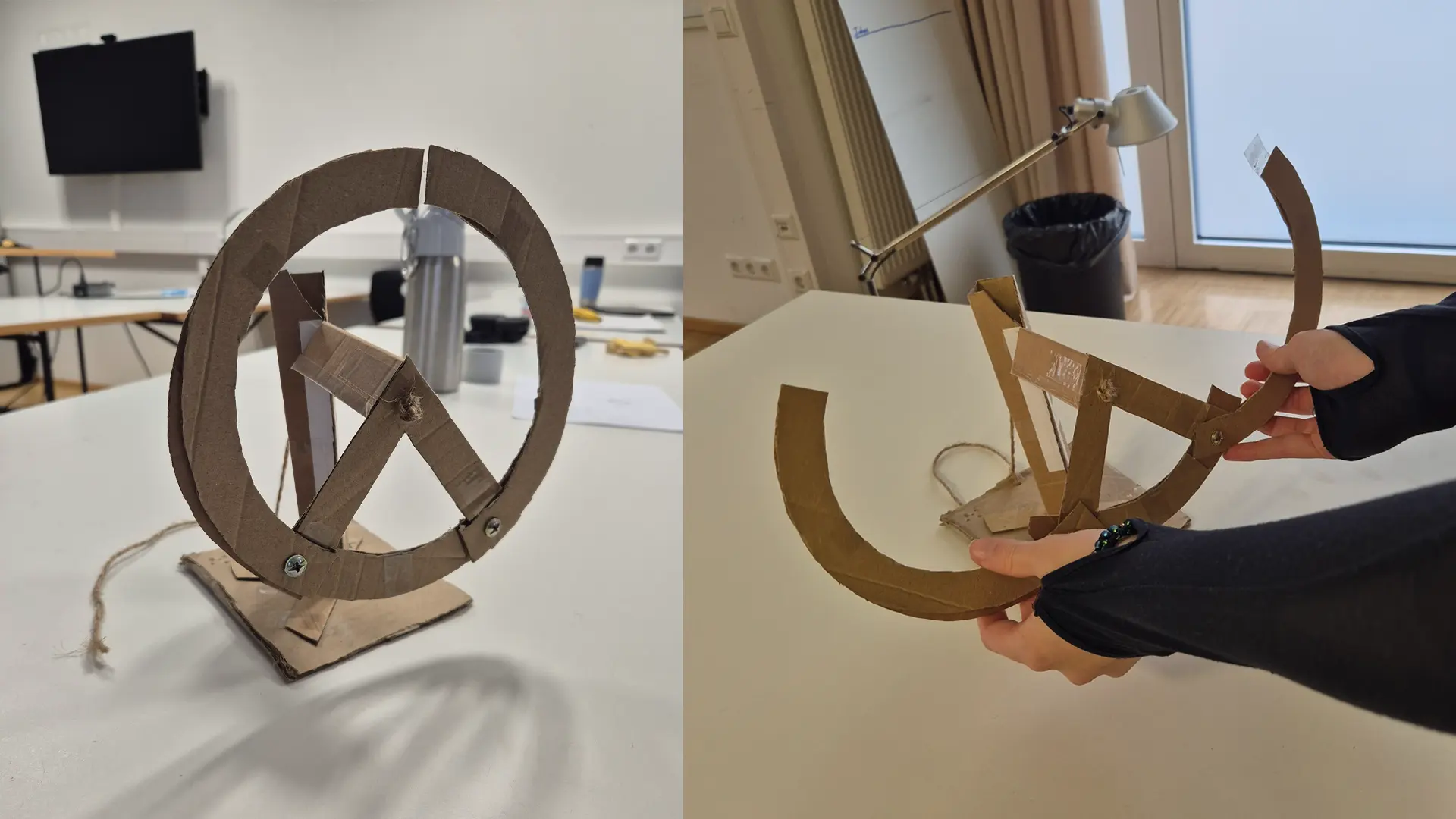
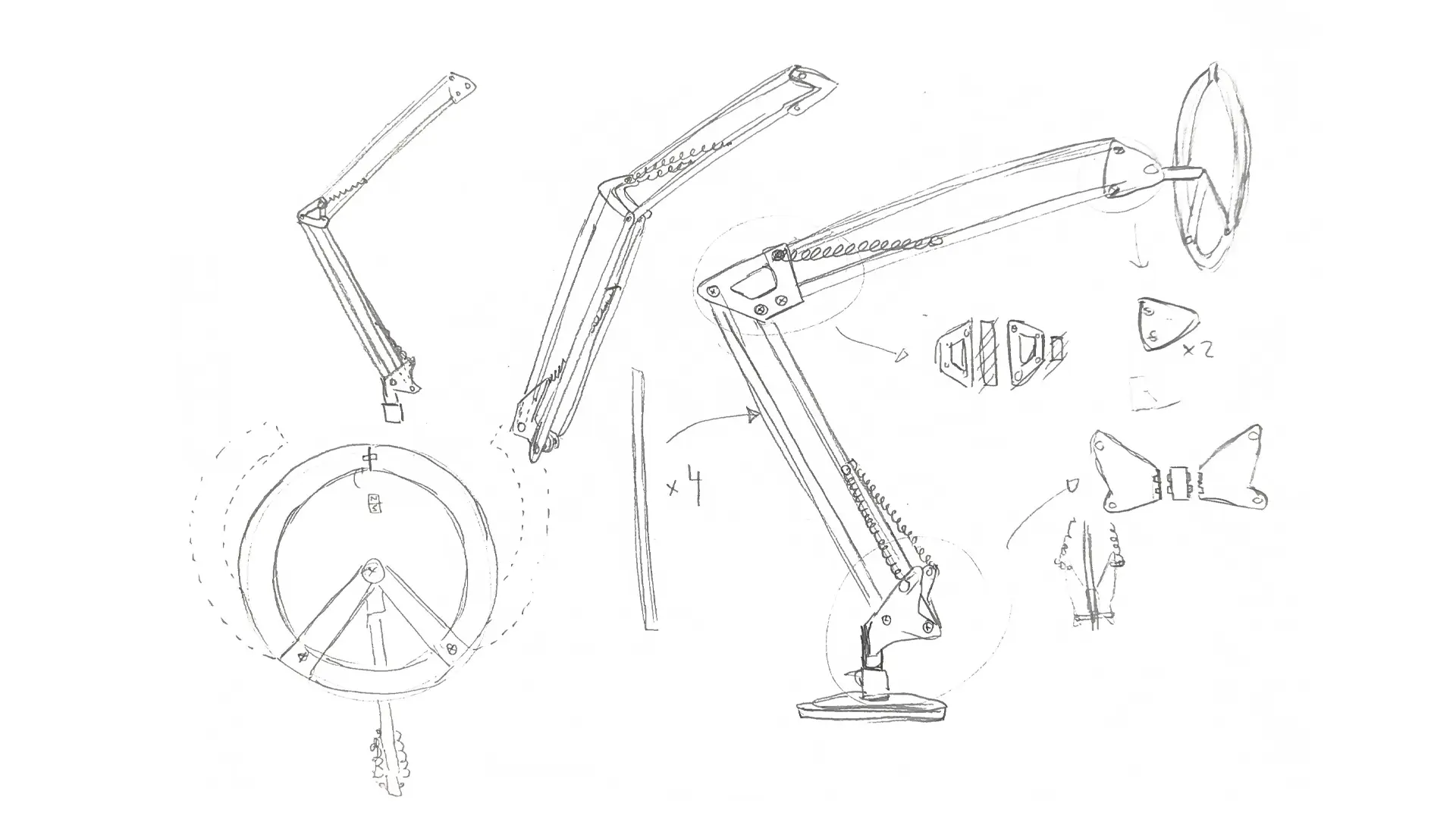
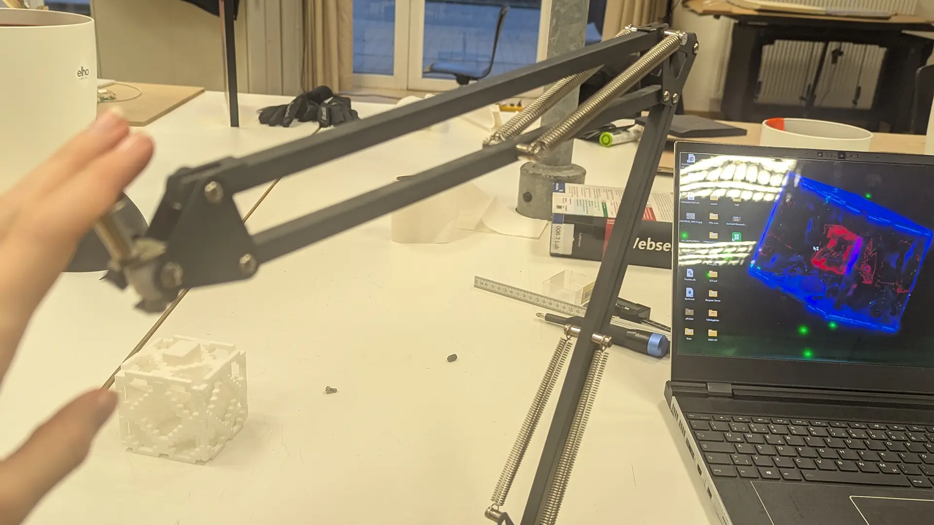
The first prototypes were cardboard models. They answered questions about the opening mechanism within minutes. In this phase came the idea to base the design on the joint mechanism of a lamp, putting the robot's forward/backward movement and the gripper arm's vertical control onto one shared system. Two rods form a parallelogram through a linkage, which keeps the upper part of the controller always parallel to the operator.
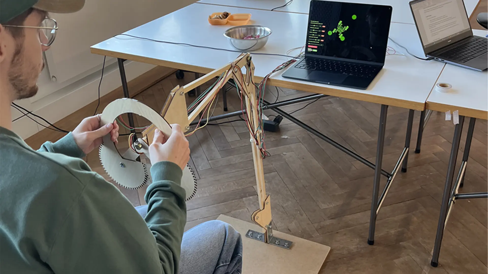
For the more stable version we switched to laser-cut wood. After several non-functional iterations, gears emerged at the lower part of the steering wheel that move both halves evenly as it opens. The movements were read out via rotary potentiometers, the opening of the gripper arm initially via a reed sensor.
The mapping
The lower joint controls forward and backward, the upper one the height of the gripper arm. Turning the steering wheel rotates the robot, opening the steering wheel opens the gripper. For the crab walk we planned a mode switch: opening the steering wheel would flip the rotation function from turning to omnidirectional movement.
What the test disproved
Testing ran on the wooden prototype against the live simulation, guided by a script of questions and observation points. In total we surveyed 16 people across two rounds, in the HfG main building on Rektor-Klaus-Straße, in the IoT lab and in our private circles. The task was to independently work out which function sat on which control.
The mode switch failed. No participant found it without help. Coupling it to the opening of the steering wheel was mechanically elegant and invisible to users. Other pain points were oversensitivity, an unclear grip position, and steering that wasn't fine enough. The rest of the mapping was correctly assigned by most people quickly.
Three approaches to the crab walk
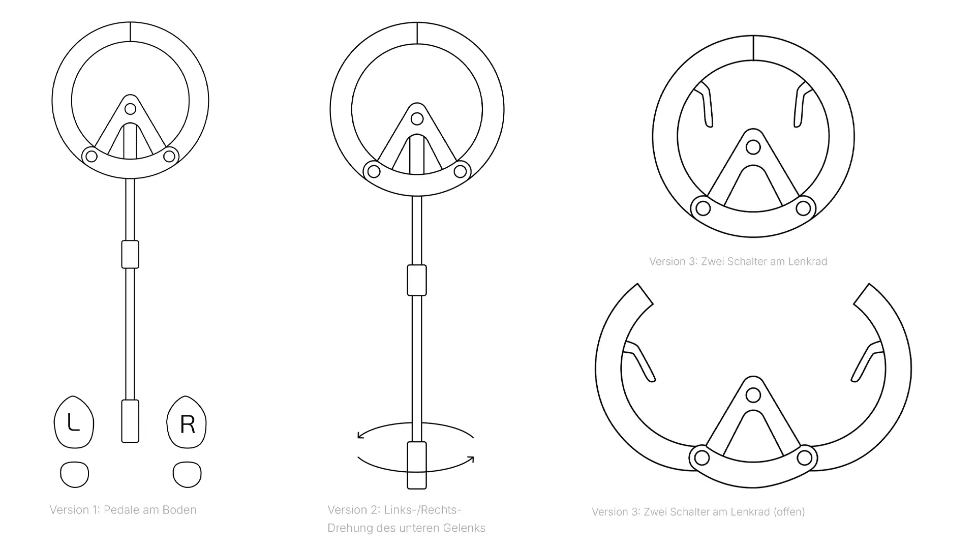
For the second, more focused round of testing we developed three alternatives and put them up for discussion: floor pedals, a left-right turn of the lower joint, and two switches on the steering wheel.
The pedals were rejected for their false association with gas pedals. An additional axis on the mount couldn't have been cleanly separated from the existing movements and would have produced faulty inputs. The clear favourite was the switches on the steering wheel, because they place the crab walk exactly where the hands already are.
03Solution
From makeshift to construction
The wooden prototype was functional but failed repeatedly during testing. The potentiometers were only plugged in rather than screwed in place, and the lower joint's zero position was held in place with rubber bands.
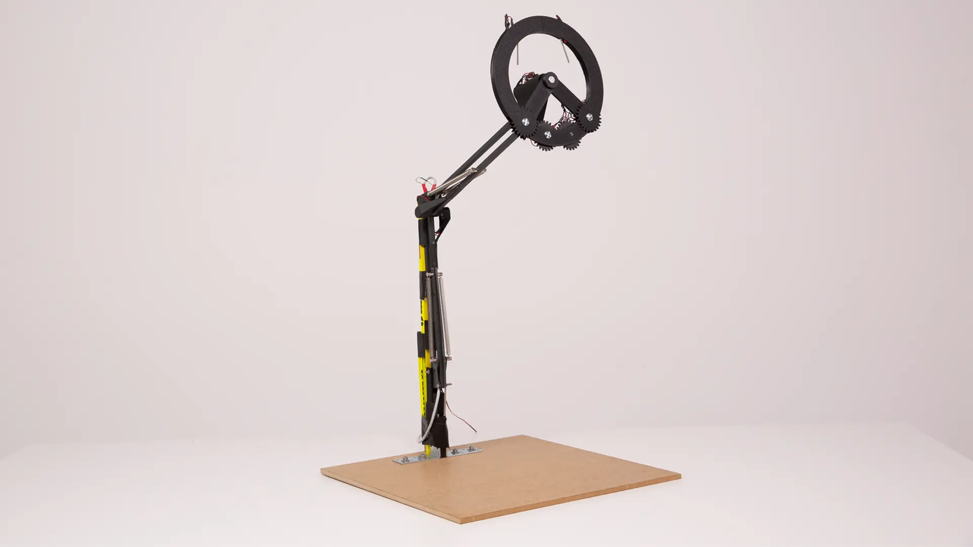
For the final build we switched from laser-cutting to 3D printing and integrated the metal frame of a lamp. The potentiometers now sit on stable axes, we replaced the reed sensor, and the steering wheel's rotation is read out via a shaft extended with two ball bearings. The crab walk now sits on two micro switches in the upper area of the steering wheel, a position we weighed against the rest of the operation.
For the zero position, after several attempts, a combination of a metal ruler, spring-steel rods and a folding rule got us there.
The design prototype
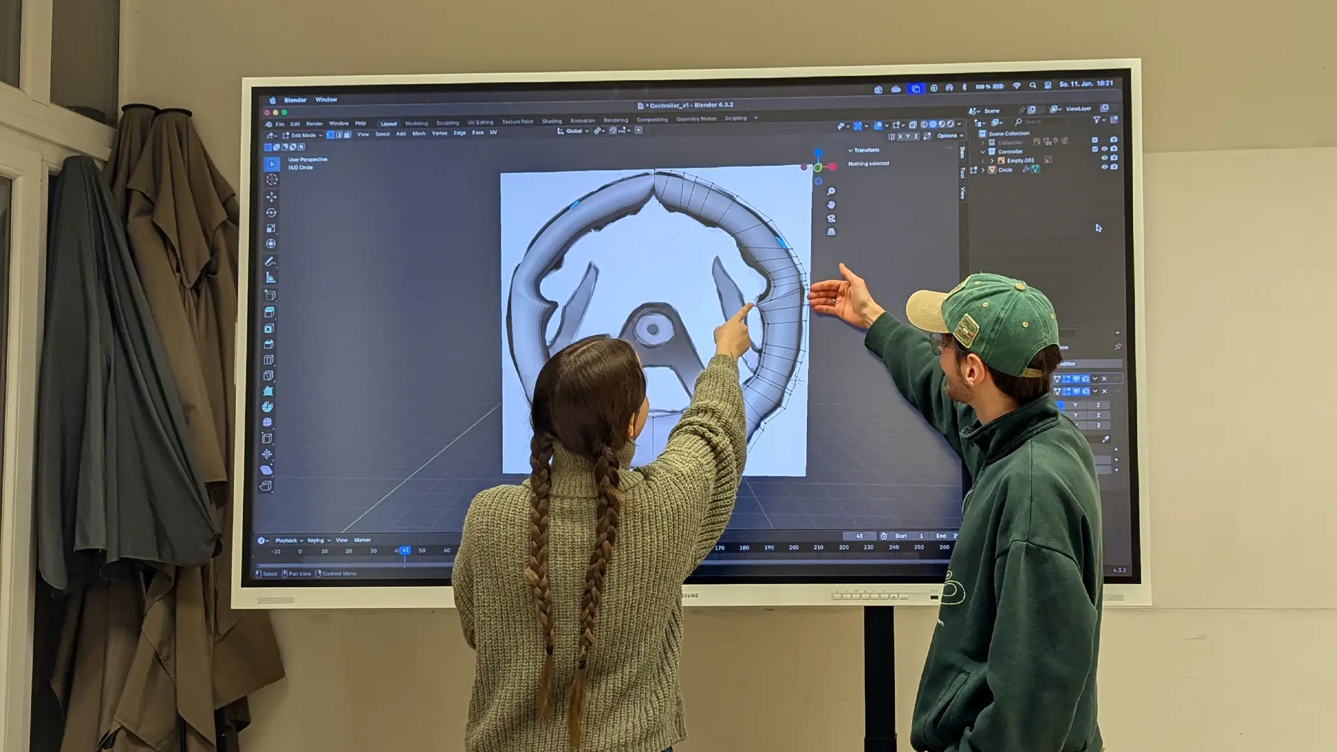
The design prototype was developed in parallel. The control element takes its form and material cues from a classic car steering wheel. The joint mechanics were carried over functionally, while the visual design leans on the aesthetic of a monitor mount. New additions are an adjustable seat on rails and a monitor with a direct view of the robot's surroundings.
Linkages, seat rails and steering wheel are made of dark grey metal, and the intended grip points are covered in black leather. This choice of material implicitly guides hand position and makes the controls recognisable without any labelling.
04Result
Result
By the end of the semester there was a working controller that maps six axes of movement without a single classic button, operable live on the simulation.
The central pain point was resolved. The mode switch, which no participant had previously found without help, was replaced by a variant that emerged as the clear favourite against two alternatives in the second round of testing. Feedback on sensitivity, steering precision and grip position fed into the hardware revision and into the material choices of the design prototype.
Learnings
The most important lesson lay in the difference between mechanical elegance and perceived logic. Coupling the mode switch to the opening of the steering wheel was structurally the cleanest solution and, in use, the weakest. Without the first round of testing it would have stayed in the final prototype.
Second, makeshift fixes at load-bearing points cost us testing time. The plugged-in potentiometers were the cause of the failures during testing and could have been fixed earlier.
Outlook
An adjustable seat, ergonomic grips and a footrest exist so far only in the design model. Also conceivable are more precise 3D constructions with integrated cable channels, and a structurally clean solution for the zero position instead of the current spring combination.
Sources
- [1] astronews.com (2006). How long does a radio signal take from Earth to the Moon?
- [2] Wikipedia, "Lichtlaufzeit" (light travel time), accessed 16 Aug 2026.
- [3] Bruno, Welz, Barnes, Sherif (1993). Analyzing Human Errors in Flight Mission Operations. NASA Technical Reports Server, N94-11534.
- [4] Thales Alenia Space (30 Jan 2025). Press release on the ESA contract for the Argonaut lunar lander's Lunar Descent Element.